FULLY BALANCED CYLINDER MODULE
(Japan Patent No. 4553977, PCT Pending)
Fully Balanced Cylinder Module Contents
1. INTRODUCTION
The Industrial Revolution of 1770s in the UK began from the invention of a reciprocating steam engine, which has been improved into gasoline engines and diesel engines during the onward developments.
For these 240 years, engineers have been aware of mechanical loss of motion in such reciprocating piston mechanism, but found no solutions.
Mazda, an automobile company, has only brought the rotary engine to the market, but it has not been successful since production technology was insufficient to obtain complete airtightness of cylinder due to constructional reasons. Then reciprocating engine still predominates in the automotive industry.
Reduction of CO2 emission is the need of the time to reduce burden to the global environment, so that development of more efficient rotating equipment with a gas or a liquid is demanded.
This is the reason why we have developed the new cylinder module.
Please find the details below.

2. TYPES OF PUMP FOR COMPRESSOR
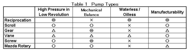
Table 1 shows the qualitative comparison of 6 major types of pump, while various types of pump exist.
n the table, Reciprocation Type is better considering "Waterless/Oilless," the need of which is recently increasing.
3. IDEAL CYLINDER
As described above, reciprocating cylinder is superior in the following aspects to other types.
(1) Easy to obtain high pressure in low revolution
(2) Facility to be simplified due to waterless and oilless construction.
(3) Easy to attain high-precision parts.
With above features, reciprocating cylinder is next to ideal one, except the defects of not small mechanical loss due to piston reciprocation and vibration noise due to imbalanced elements.
Then we here examine piston reciprocating motion in order to understand the reason of large mechanical loss and vibration.
See Figs. 1 and 2 to consider rough trend of such mechanical loss through simplified calculation. This piston shown in Fig. 1 is a simplified model, since the purpose of this calculation isn't to obtain the value of mechanical loss in piston reciprocating motion.
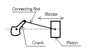
Fig. 1 Concept of Reciprocating Piston
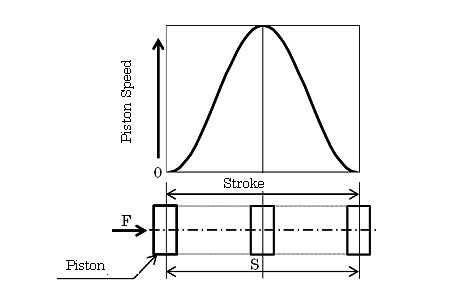
Fig. 2 Analysis Model
Where
S:Stroke length
t:Time for stroke travel
m:Piston mass
F:Force to drive piston
α:Acceleration
In Fig. 2,
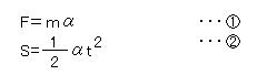
Then the values of S, t and m should be known to obtain the driving force F, which is the mechanical loss to be consumed in piston reciprocation.
Considering piston travel time in inverse proportion to the number of revolutions of the unit using the reciprocating piston, the mechanical loss of such reciprocating motion increases:
● In proportion to the mass of piston; and
● In proportion to the square of number of revolutions.
4. FULLY BALANCED CYLINDER
Appearance and parts of a fully balanced cylinder module are shown in Fig. 3. This new cylinder unit with reciprocating pistons has been developed to remove mechanical loss.
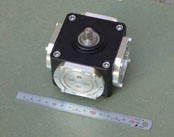 Appearance |
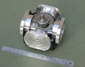 Dismantled |
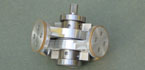 Crank Piston  Crank Piston |
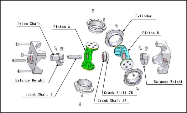
(1) Principle of Linear Reciprocating Motion
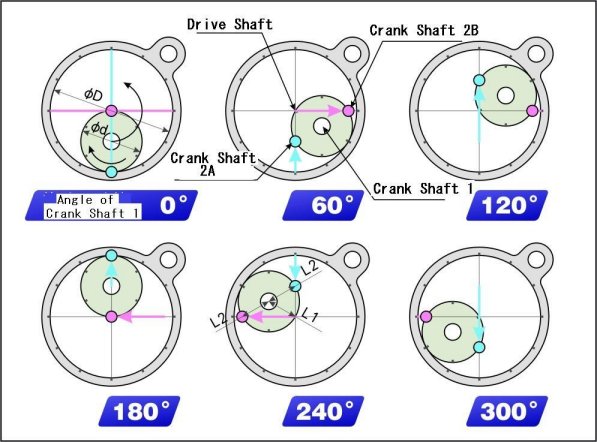
In general, where a movable circle rotates inscribed to a fixed circle without slip, the locus of a fixed point on the perimeter of the movable circle draws hypocycloid curve. If the ratio of the diameter D of the fixed circle against the diameter of the movable circle d is 2:1, the locus of the point falls into a straight line.
In this principle, by fixing the distance between Drive Shaft and Crankshaft 1 to L1 (L1=0.5 d), the distance between Crankshaft 1 and each of Crankshafts 2 (A and B) to L2 (L2=L1=0.5 d), and controlling the motion of each Crankshaft 2 (A, B) to linear reciprocating motion, the fixed and the movable circles can be omitted.
This mechanism converts between revolving motion of Crankshaft 1 and linear reciprocating motion of Crankshafts 2 (A and B).
(2) Constant Speed Rotation of Movable Part
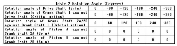
In fig. 4 where each of Crank Shafts 2A and 2B runs in linear reciprocating motion, assume to assemble a linear piston with each shaft.
Clockwise rotation is shown with "+" and counterclockwise rotation with "-," rotation angle is shown in an absolute coordinate system.
 |
 |
As shown in Table 2, every movable part for the cylinder theoretically runs constant speed motion around its rotation axis.
(3) Principle of Canceling Decentering
Considering constant speed motion described above, achieve balances as shown below to cancel decentering.
1) Balance 1: Achieve balance of each of Pistons A and B around Crank Shaft 2.
2) Balance 2: Achieve balance of each piston and each of Crank Shafts 2A and 2B around Crank shaft 1.
3) Balance 3: Put a balance weight on Drive Shaft to achieve balances of all movable parts around the shaft.
An ideal cylinder without mechanical loss due to piston reciprocating motion is realized by reflecting the above paragraphs (1) to (3) to the design of cylinder.
(4) Actual Effects
The new Fully Balanced Cylinder, without mechanical loss of piston reciprocating motion, has the following features:
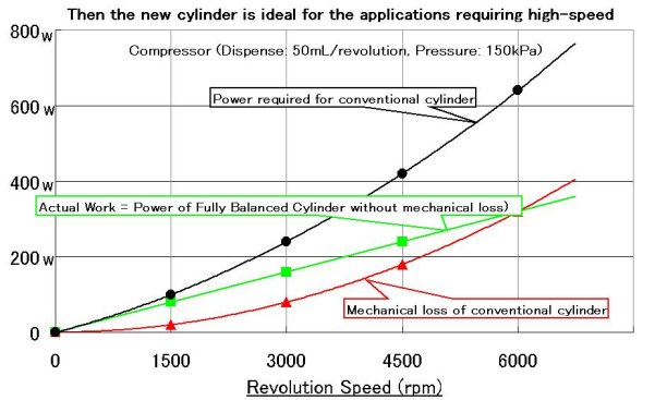
1) High efficient (See Fig. 5)
2) Less vibration and noise (Vibration and noise induced from piston reciprocation are removed.)
3) Compact and light-weight
Then the new cylinder is ideal for the applications requiring high-speed rotation.
 |
(5) Applications
This new cylinder is replaceable with all of rotary compressor, scroll compressor, screw compressor and reciprocating compressor.
Major applications are:
1) General internal-combustion engine
2) Pneumatic compressor (air conditioner, refrigerator)
3) Vacuum pump
4) Fluid pump for gas and liquid
5) Motor using gas or liquid pressure
6) Turbo pump and turbine
The new cylinder with silentness and less energy consumption covers wide applications including medical industry.
5. FUTURE EXPANSION
We have spent almost 20 years to develop this new cylinder. Additional elements will be required for the expansion to further applications, while fundamental construction and principle remain unchanged.